General Knowledge of Batteries
We provide information for customers
who wish to know more about batteries.
Car Battery Structure
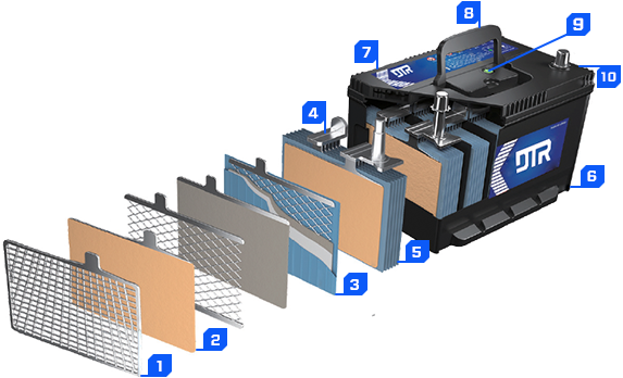
Battery Structure
1
GRID2
PLATE3
ENV.SEPARATOR4
STRAP5
ELEMENT6
CONTAINER-B.P7
FINAL COVER8
MAIN COVER9
INDICATOR10
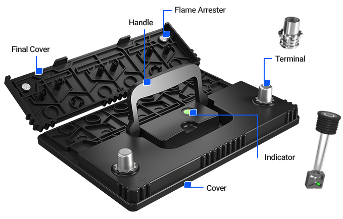
TERMINAL
-
GRID
A lead alloy board that supports active material and conducts generated electricity.
-
Active Material
A material that reacts with sulfuric acid to charge and discharge
-

Positive Plate
When active material is applied on the positive grid
-
Negative Plate
When active material is applied on the negative grid
-
Electroseparator
Placed between the positive and negative plates to prevent short-circuits due to direct contact.
In particular, the envelope electroseparators wrap the negativeplates to prevent short-circuits with the positive plates due to the active material
-
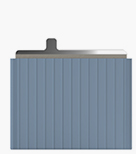
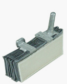
Pole Plate Group
A group of pole plates welded to the strap, stacked in order of a positive pole plate, separator, and negative pole plate.
- The electromotive force per cell is 2V. Voltage is kept steady regardless of the size or number of pole plates.
- The 12V battery used for cars has 6 pole plate groups connected in a series in the container.
-
Electrolyte
The electrolyte causes the positive and negative pole plates to react and generate electricity, and also acts as an electrical conductor.
-
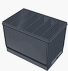
Container
A container which is usually made of plastic contains an electrolyte and the pole plate group.
- It is separated internally by walls (12V →6 divisions / 6V →3 divisions) and the bottom of the container is attached with an inner layer.
Other Parts
-
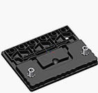
Main Cover
A part that covers the top of the container
to prevent electrolyte in the battery from leaking.
The main cover has filling holes to fill electrolyte,
and return holes to release gas and steam.
-
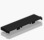
Final Cover
A part that spreads over the top of the main cover
The gas and steam emitted through the return hole are separated
through a labyrinth structure. The sulfuric acid steam is returned
to the battery, and gases (hydrogen, oxygen) are released through
the vent hole.
-
Flame Arrester
Equipment installed on the inside of the final cover
for anti-explosive functions.
The released gases (hydrogen, oxygen) are flammable. Before they are
released through the vent hole, the flame arrester, made of a dense
bubble structure, decreases the cross-section areas to prevent the
explosion.
-
Indicator
Equipment installed on the top area of the main cover to show
the status of the battery
- Green : Normal, charged 50% or higher
- Black : Charging required, charged 50% or lower
- White : End of life (B/T replacement)